RAMPS-FD Conversion
DupI3.RAMPS-FDConversion History
Hide minor edits - Show changes to markup
configuration Part 3-5:
configuration Part 3-5: (Skip this step. The Dropbox download already has it done)
(file placeholder)
(Installing Repetier firmware: RAMPSFD-work092)
(Installing Repetier firmware: RAMPSFD-EEPROM)
open your unzipped repetier-firmware-RAMPSFD-work092 folder
open your unzipped repetier-firmware-RAMPSFD-EEPROM folder
Repetier-firmware-RAMPSFD-work092\\
Repetier-firmware-RAMPSFD-EEPROM with EEPROM Support. Configured for Geeetech v1.2 or earlier\\
|Arduino Due board information
Arduino Due board information
Aluminum Heatsink\\
Aluminum Heatsink from Amazon\\
Copper Heatsink
Copper Heatsink from Amazon
http://www.amazon.com/gp/product/B0009IQ1BU/ref=ox_sc_act_title_1?ie=UTF8&psc=1&smid=A2EUTVCJXLAJ4K
Heatsink Thermal Adhesive from Amazon
https://www.arduino.cc/en/Main/arduinoBoardDue
|Arduino Due board information
http://www.amazon.com/Cosmos-Copper-Cooling-Heatsinks-cooler/dp/B00637X42A
Cosmos Copper Cooling Heatsinks
http://www.amazon.com/s/ref=sr_nr_n_0?fst=as%3Aoff&rh=n%3A16310091%2Cn%3A8481414011%2Ck%3ALCD+Smart+controller&keywords=LCD+Smart+controller&ie=UTF8&qid=1439847057&rnid=16310161
Reprap LCD Smart Controller
http://www.amazon.com/Geeetech-Adapter-Adruino-Ramps-FD-Control/dp/B00U22ILCA/ref=sr_1_cc_3?s=aps&ie=UTF8&qid=1439849586&sr=1-3-catcorr&keywords=ramps-fd
Ramps-FD LCD Adapter
http://www.amazon.com/iXCC-FEET-Premium-Speed-Extra/dp/B00MVAO742/ref=sr_1_4?&s=pc&ie=UTF8&qid=1439862255&sr=1-4&keywords=micro+usb+to+usb
Micro USB to USB Male Cable
http://www.thingiverse.com/thing:958393
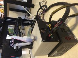
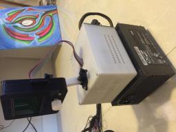
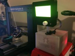
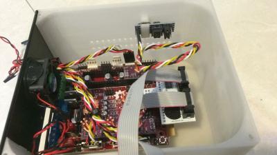
Printable Ramps-fd Enclosure by Delukart
- or:
->Copper Heatsink
Aluminum Heatsink
or:
Copper Heatsink
(aluminum)
http://www.amazon.com/11x11x5mm-heatsink-StepStick-stepper-drivers/dp/B00AO04I5Y
(copper):
http://www.amazon.com/Enzotech-MOS-C10-Forged-Copper-Heatsinks/dp/B004CL89D8/ref=pd_sim_147_3?ie=UTF8&refRID=07DX27YR5VBNE6P02D6B
installing the steppers for x.y.z.
notice the orientation of the processor chips in the pictures below .
(they face the power block towards the back)
and the extruder stepper driver processor chip faces the opposite way.
(it faces the display adapter)
installing the steppers for X.Y.Z.E.
notice the orientation of the X.Y.Z processor chips in the pictures below .
(they face the power block towards the back)
the E. processor chip faces the opposite way.
(it faces the display adapter)
(see pictures below)
Putting it all together Part 2-5:\\
Putting it all together Part 2-5:
- steppers /end stops /temp sensors
https://www.youtube.com/watch?v=uPKH4q_zEbw
- steppers /end stops /temp sensors
https://www.youtube.com/watch?v=uPKH4q_zEbw\\
(read and follow the instructions for the Arduino due)\\
- (read and follow the instructions for the Arduino due)\\
Installing the EEPROM to the ramps-fd:\\
- Installing the EEPROM to the ramps-fd:\\
(always use heatshrink over every soldered joint on every wire.!!!!)
(always use heat shrink tubing over every soldered joint on every wire.!!!!)
steppers /end stops /temp sensors
- steppers /end stops /temp sensors
- or these:\\ http://www.amazon.com/FbscTech-Female-Jumper-Dupont-Printer/dp/B00KWA1RJ6/ref=pd_sxp_redirect/180-4817561-8727630
- or these:
http://www.amazon.com/FbscTech-Female-Jumper-Dupont-Printer/dp/B00KWA1RJ6/ref=pd_sxp_redirect/180-4817561-8727630
- (aluminum)
http://www.amazon.com/11x11x5mm-heatsink-StepStick-stepper-drivers/dp/B00AO04I5Y\\
(aluminum)
http://www.amazon.com/11x11x5mm-heatsink-StepStick-stepper-drivers/dp/B00AO04I5Y
- (copper):\\
(copper):\\
http://www.amazon.com/Cosmos-Copper-Cooling-Heatsinks-cooler/dp/B00637X42A?
http://www.amazon.com/Cosmos-Copper-Cooling-Heatsinks-cooler/dp/B00637X42A
- (you might want to print this while you wait for your parts to arrive)\\
(you might want to print this while you wait for your parts to arrive)\\
Stepper Driver Heatsinks:
(aluminum)\\
- Stepper Driver Heatsinks:
*(aluminum)\\
or:
(copper):\\
- or:
*(copper):\\
heatsink thermal adhesive:\\
- heatsink thermal adhesive:\\
Arduino Due:\\
- Arduino Due:\\
processor heatsinks:\\(I used 4 on my due atmega chip and 1 on my ramps-fd processor chip)\\
- processor heatsinks:\\(I used 4 on my due atmega chip and 1 on my ramps-fd processor chip)\\
LCD Smart controller:(there are many to choose from)\\
- LCD Smart controller:(there are many to choose from)\\
LCD Smart controller adapter:(for ramps-fd)\\
- LCD Smart controller adapter:(for ramps-fd)\\
connectors:(for end stops and temp sensors and fans)\\
- connectors:(for end stops and temp sensors and fans)\\
or these:\\ http://www.amazon.com/FbscTech-Female-Jumper-Dupont-Printer/dp/B00KWA1RJ6/ref=pd_sxp_redirect/180-4817561-8727630
connectors:(for stepper motors and eeprom)\\
- or these:\\ http://www.amazon.com/FbscTech-Female-Jumper-Dupont-Printer/dp/B00KWA1RJ6/ref=pd_sxp_redirect/180-4817561-8727630
- connectors:(for stepper motors and eeprom)\\
usb interface cable:(any micro usb to usb cable will do)\\
- usb interface cable:(any micro usb to usb cable will do)\\
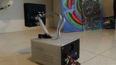
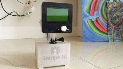
optional printable ramps-fd enclosure:
(you might want to print this while you wait for your parts to arrive)\\
- optional printable ramps-fd enclosure:
*(you might want to print this while you wait for your parts to arrive)\\
'*Stepper driver trimpot adjustment ceramic screwdriver:'\\
- Stepper driver trimpot adjustment ceramic screwdriver:\\
Stepper Drivers:(You will need at least 4 DRV8825)
http://www.geeetech.com/stepstick-drv8825-stepper-motor-driver-carrier-reprap-4layer-pcb-p-652.html?zenid=od3bt94m1u5j4bc4vr4jjibbv5
Stepper driver trimpot adjustment ceramic screwdriver:
http://e3d-online.com/index.php?route=product/product&product_id=356
- Stepper Drivers:(You will need at least 4 DRV8825)
DRV8825 Stepper Drivers / Carrier board
'*Stepper driver trimpot adjustment ceramic screwdriver:'
Ceramic screwdriver from e3d-online
Printer Controller Board:(ramps-fd)
*Geetech Ramps-FD Controller Shield
EEPROM for Firmware setting storage:
*I2C EEPROM Board
- Printer Controller Board:(ramps-fd)
Geetech Ramps-FD Controller Shield - EEPROM for Firmware setting storage:
I2C EEPROM Board
Geetech Ramps-FD Controller Shield
- Geetech Ramps-FD Controller Shield
I2C EEPROM Board
- I2C EEPROM Board
http://www.geeetech.com/new-pololu-shield-rampsfd-for-arduino-due-3d-printer-controller-p-770.html
EEPROM:
http://www.amazon.com/gp/product/B00S4UFUEE?psc=1&redirect=true&ref_=ox_sc_act_title_1&smid=A1THAZDOWP300U
Geetech Ramps-FD Controller Shield
EEPROM for Firmware setting storage:
I2C EEPROM Board
next level your plate..
then start printing!!!
next level your plate..
now start printing!!!
then you can unplug the due ...
you can now unplug the due from the computer ...
your ramps-fd and due is now set up and ready.
Part 5:
wiring up the ramps fd:
wiring part5-1:
steppers /end stops /temp sensors
https://www.youtube.com/watch?v=uPKH4q_zEbw
wiring part5-2:
extruder fan /cooling fan /case fan
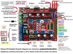
the extruder fan connects to the extra mosfet (D2) terminal
the pla cooling fan connects to the extra mosfet (D12) terminal
the case fan connects to the aux terminal next to the x stepper driver
wiring part5-3:
installing the psu.
if you notice in the diagram the ramps-fd takes 3 sets of positive and negative wires to power the board.
they go to the 12-24v in rails for the board stepper power the heaters power and the heat bed power.
wiring part5-4:
installing the hot end and the heat bed.
the heat bed goes to the heat bed (d8)12-24v out socket.
and the extruder heater(hot end) goes to the extruder/ E1(D9)
socket.
well now your all wired up …
part6.
voltage adjustments
voltage part6-1
adjusting your stepper driver trimpot voltage.
power up your printer and get out your digital multi meter
out and set to dc volts.
(i set mine to 20 dc volts)
and your ceramic screwdriver(desighned for stepper driver trimpots).
now connect your negative terminal from your multi meter to the negative terminal on your powered up ramps-fd board.
then for each stepper insert the ceramic screw driver into the trim pot and touch the top of the trimpot with the positive terminal from your multi meter.
you are going to adjust one at a time the x y and z steppers to
X and Y 0.5- 0.6V
Z axis 0.5 to 0.55V
and the extruder stepper to
Extruder 0.6-065V
trimpot adjustments are.
to lower voltage is clockwise.
and to bring the voltage higher is counter clockwise..
(the trimpots are very sensitive and just turning a tiny bit moves the voltage a lot. so be careful..)
Now you are ready to hook up to repetier host to check and change any eeprom settings that you need to.
(like e-steps whitch are doubled now that you are running 1/32 stepps compared to the original 1/16 stepps)
next level your plate..
then start printing!!!
Hardware / Parts
Duplicator i3 Ramps-fd
The switch over.
by.Mark Rattelade (delukart)
installing the steppers for x.y.z.
notice the orientation of the processor chips in the pictures below .
(they face the power block towards the back)
and the extruder stepper driver processor chip faces the opposite way.
(it faces the display adapter)
Putting it all together Part 2-3:\\
Putting it all together Part 2-3:
installing the steppers for x.y.z.
notice the orientation of the processor chips in the pictures below .
(they face the power block towards the back)
and the extruder stepper driver processor chip faces the opposite way.
(it faces the display adapter)
Putting it all together Part 2-4:\\
Putting it all together Part 2-4:\\
Putting it all together Part 2-5:\\
Putting it all together Part 2-5:\\
Putting it all together Part 2-6:\\
Putting it all together Part 2-6:\\
Putting it all together Part 2-7:\\
"""(always use heatshrink over every soldered joint on every wire.!!!!)'''
(always use heatshrink over every soldered joint on every wire.!!!!)
soldering Part 4-1: soldering the stepper motors: all wires are soldered inline .(start on one side of the connector and solder the first wire from your stepper motor the first wire of the connector. and the second wire from your stepper motor to the second wire of the connector. and so on. (make sure not to cross any wires) (do 1 wire at a time.) (and label each new connector as you solder them) you dont want to chase down leads all night.
soldering Part 4-2: soldering the end stops and the temp sensors: they are not polarity sensitive. just solder one wire from the end stop to a wire on the plug . then solder the next wire from the end stop to the other wire on the plug. soldering Part 4-3: soldering the fans the wires are polarity sensitive and must be inline. solder + to red wire on the plug and solder - to black wire on the plug
soldering Part 4-1:
soldering the stepper motors:
all wires are soldered inline.
(start on one side of the connector and solder the first wire from your stepper motor the first wire of the connector.)
and the second wire from your stepper motor to the second wire of the connector. and so on.
(make sure not to cross any wires)
(do 1 wire at a time.)
(and label each new connector as you solder them)
you dont want to chase down leads all night.
soldering Part 4-2:
soldering the end stops and the temp sensors:
they are not polarity sensitive.
just solder one wire from the end stop to a wire on the plug .
then solder the next wire from the end stop to the other wire on the plug.
soldering Part 4-3:
soldering the fans
the wires are polarity sensitive and must be inline.
solder + to red wire on the plug and
solder - to black wire on the plug
Part 4:
soldering the existing wires from your i3 to the new connectors:
"""(always use heatshrink over every soldered joint on every wire.!!!!)'''
soldering Part 4-1: soldering the stepper motors: all wires are soldered inline .(start on one side of the connector and solder the first wire from your stepper motor the first wire of the connector. and the second wire from your stepper motor to the second wire of the connector. and so on. (make sure not to cross any wires) (do 1 wire at a time.) (and label each new connector as you solder them) you dont want to chase down leads all night.
soldering Part 4-2: soldering the end stops and the temp sensors: they are not polarity sensitive. just solder one wire from the end stop to a wire on the plug . then solder the next wire from the end stop to the other wire on the plug. soldering Part 4-3: soldering the fans the wires are polarity sensitive and must be inline. solder + to red wire on the plug and solder - to black wire on the plug
Part 1.
Getting the right parts
..(all parts can also be found on amazon)
Part 1.
Getting the right parts
..(all parts can also be found on amazon)
Putting it all together Part 2-1:\\
Putting it all together Part 2-1:
part 3.
configuring your repetier firmware:
(Installing Repetier firmware: RAMPSFD-work092)
configuration Part 3-1:
connect ramps-fd to your computer from the programing port of your due.
(closest to the power plug).
(make sure you have the eeprom/stepper drivers/display connected)
also:
(plugging in the usb from the computer to the due will power up the ramps-fd motherboard)
(do not open the arduino control panel)
configuration Part 3-2:
open your unzipped repetier-firmware-RAMPSFD-work092 folder
then look for and open.
src/Arduino DUE/and click on the repetier arduino file.
( the one with the green arduino icon).
configuration Part 3-3:
the arduino controle panel should open.
((now make sure your due and computer are connected and talking))
configuration Part 3-4:
go to configuration.h
and look for drive_system 1
(close to the top of the lines of code)
drive_system 1
change it to
drive_system 0
next scroll down to about half the page and look for:
ui_Printer_name “ryan”
change it to
ui_Printer_Name “d-i3” ( or what ever you want to change it to)
and right under that look for:
ui_Printer_Company “carlyle”
change it to
ui_Printer_company “Wanhao” ( or what ever you want to change it to)
configuration Part 3-5:
go to pins.h
and scroll down till you see
/******************************************************/
//RAMPS-FD board
//
now look a little bit further down for:
if Motherboard == 403
//if Motherboard == 404
change it to
//if Motherboard == 403
if Motherboard == 404
configuration Part 3-6:
now that everything is configured and your due and your computer are hooked up and talking:
up at the top left corner of the arduino control panel there is an arrow to the right of the check mark in the corner.
that is the upload button.
click it and wait..
at the bottom of the arduino control panel you should be able to see in red the system updating the.
due/ramps-fd/display/steppers/and the eeprom.
once it is done and says reset.
then you can unplug the due ...
bringing your Due to life:\\
bringing your Due to life:
Part 1. Getting the right parts..(all parts can also be found on amazon)
Part 1.
Getting the right parts
..(all parts can also be found on amazon)
Part2:\\ Puting it all together\\
Part2:
Puting it all together
as in the diagram further down in pictures.[<<]] also a jumper should be on the jp1 vin\\ (to power the arduino from the
as in the diagram further down in pictures.
also a jumper should be on the jp1 vin
(to power the arduino from the
making sure all your jumpers are hooked up and set correctly:
under the x stepper driver make sure the jumpers are set correctly.
jumper for iorf and 5v logic should be set to the iorf side
as in the diagram further down in pictures.\\
making sure all your jumpers are hooked up and set correctly:
under the x stepper driver make sure the jumpers are set correctly.
jumper for iorf and 5v logic should be set to the iorf side
as in the diagram further down in pictures.[<<]]
psu connected to the ramps-fd and not the usb.)
also notice the 12v 24v jumper just outside the x stepper.\\ the jumper should be set for 12v not 24v.
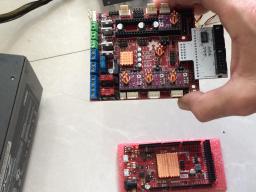
installing the steppers for x.y.z.\\ notice the orientation of the processor chips in the pictures below .\\ (they face the power block towards the back)\\ and the extruder stepper driver processor chip faces the opposite way.\\ (it faces the display adapter)\\
psu connected to the ramps-fd and not the usb.)
also notice the 12v 24v jumper just outside the x stepper.
the jumper should be set for 12v not 24v.
installing the steppers for x.y.z.
notice the orientation of the processor chips in the pictures below .
(they face the power block towards the back)
and the extruder stepper driver processor chip faces the opposite way.
(it faces the display adapter)
Part 1.
Part 1.
Part2: Puting it all together
Putting it all together Part 2-1: bringing your Due to life: (read and follow the instructions for the Arduino due) https://www.arduino.cc/en/Guide/ArduinoDue
Part2:\\ Puting it all together
Putting it all together Part 2-1:\\
bringing your Due to life:
(read and follow the instructions for the Arduino due)
https://www.arduino.cc/en/Guide/ArduinoDue
Putting it all together Part 2-2: making sure all your jumpers are hooked up and set correctly:
under the x stepper driver make sure the jumpers are set correctly. jumper for iorf and 5v logic should be set to the iorf side as in the diagram further down on page 10. also a jumper should be on the jp1 vin (to power the arduino from the psu connected to the ramps-fd and not the usb. also notice the 12v 24v jumper just outside the x stepper. the jumper should be set for 12v not 24v.
installing the steppers for x.y.z. notice the orientation of the processor chips in the pictures below . (they face the power block towards the back) and the extruder stepper driver processor chip faces the opposite way (faces the display adaptor)
Putting it all together Part 2-2:
making sure all your jumpers are hooked up and set correctly:
under the x stepper driver make sure the jumpers are set correctly.
jumper for iorf and 5v logic should be set to the iorf side
as in the diagram further down in pictures.
also a jumper should be on the jp1 vin\\ (to power the arduino from the
psu connected to the ramps-fd and not the usb.)
also notice the 12v 24v jumper just outside the x stepper.\\ the jumper should be set for 12v not 24v.
installing the steppers for x.y.z.\\ notice the orientation of the processor chips in the pictures below .\\ (they face the power block towards the back)\\ and the extruder stepper driver processor chip faces the opposite way.\\ (it faces the display adapter)\\
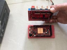
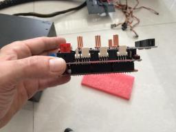
Putting it all together Part 2-3: Mounting the ramps-fd to the due: (see pictures below)
Putting it all together Part 2-3:
Mounting the ramps-fd to the due:
(see pictures below)
Putting it all together Part 2-4: Installing the EEPROM to the ramps-fd:(video) https://www.youtube.com/watch?v=UkMb9qCuHms
Putting it all together Part 2-4:
Installing the EEPROM to the ramps-fd:
https://www.youtube.com/watch?v=UkMb9qCuHms
Putting it all together Part 2-5: download the firmware: Repetier-firmware-RAMPSFD-work092
(credit goes to james armstrong for this firmware and for helping us bring our duplicator i3 ramps-fd to life. )
(file placeholder)
Putting it all together Part 2-5:
download the firmware:
Repetier-firmware-RAMPSFD-work092
(credit goes to james armstrong for this firmware and for helping us bring our duplicator i3 ramps-fd's to life. )
(file placeholder)\\
Putting it all together Part 2-6: installing the lcd controller driver:
(search for your display drivers from the manufacturer and download them and unzip them).
next copy and paste the unzipped display folder into.
Program Files (x86)/Arduino/libraries(or wherever you installed the Arduino program in your computer)
(example--my display used U8glib drivers)
Putting it all together Part 2-6:
installing the lcd controller driver:
(search for your display drivers from the manufacturer and download them and unzip them).
next copy and paste the unzipped display folder into.
Program Files (x86)/Arduino/libraries(or wherever you installed the Arduino program in your computer)\\
(example--my display used U8glib drivers)\\
Printer Controller Board:(ramps-fd)
Printer Controller Board:(ramps-fd)\\
EEPROM:
EEPROM:\\
Stepper Drivers:(You will need at least 4 DRV8825)
Stepper Drivers:(You will need at least 4 DRV8825)\\
Stepper driver trimpot adjustment ceramic screwdriver:
Stepper driver trimpot adjustment ceramic screwdriver:\\
Stepper Driver Heatsinks: (aluminum) http://www.amazon.com/11x11x5mm-heatsink-StepStick-stepper-drivers/dp/B00AO04I5Y or: (copper):
Stepper Driver Heatsinks:
(aluminum)
http://www.amazon.com/11x11x5mm-heatsink-StepStick-stepper-drivers/dp/B00AO04I5Y\\
or:
(copper):\\
heatsink thermal adhesive:
heatsink thermal adhesive:\\
Arduino Due:
Arduino Due:\\
processor heatsinks:(I used 4 on my due atmega chip and 1 on my ramps-fd processor chip)
processor heatsinks:\\(I used 4 on my due atmega chip and 1 on my ramps-fd processor chip)\\
LCD Smart controller:(there are many to choose from)
LCD Smart controller:(there are many to choose from)\\
LCD Smart controller adapter:(for ramps-fd)
LCD Smart controller adapter:(for ramps-fd)\\
connectors:(for endstops and thermistors and fans) http://www.amazon.com/gp/product/B00CQE90PY/ref=ox_sc_act_title_1?ie=UTF8&psc=1&smid=A3UJU66UCNEADW or these: http://www.amazon.com/FbscTech-Female-Jumper-Dupont-Printer/dp/B00KWA1RJ6/ref=pd_sxp_redirect/180-4817561-8727630
connectors:(for stepper motors and eeprom)
connectors:(for end stops and temp sensors and fans)
http://www.amazon.com/gp/product/B00CQE90PY/ref=ox_sc_act_title_1?ie=UTF8&psc=1&smid=A3UJU66UCNEADW
or these:\\ http://www.amazon.com/FbscTech-Female-Jumper-Dupont-Printer/dp/B00KWA1RJ6/ref=pd_sxp_redirect/180-4817561-8727630
connectors:(for stepper motors and eeprom)\\
usb interface cable:(any micro usb to usb cable will do)
usb interface cable:(any micro usb to usb cable will do)\\
optional printable ramps-fd enclosure: (you might want to print this while you wait for your parts to arrive)
optional printable ramps-fd enclosure:
(you might want to print this while you wait for your parts to arrive)\\
next copy and paste the unzipped display folder
in Program Files (x86)/Arduino/libraries(or wherever you installed the Arduino program in your computer)
next copy and paste the unzipped display folder into.
Program Files (x86)/Arduino/libraries(or wherever you installed the Arduino program in your computer)
Part2: Puting it all together
Putting it all together Part 2-1:
Part2: Puting it all together
Putting it all together Part 2-1:
Putting it all together Part 2-2:
Putting it all together Part 2-2:
Putting it all together Part 2-3:
Putting it all together Part 2-3:
Putting it all together Part 2-4:
Putting it all together Part 2-4:
Putting it all together Part 2-5:
Putting it all together Part 2-5:
Putting it all together Part 2-6:
Putting it all together Part 2-6:
 next  copy and paste the unzipped display folder
 in Program Files (x86)/Arduino/libraries(or wherever you installed the Arduino program in your computer) (example--my display used U8glib drivers)
 next  copy and paste the unzipped display folder
 in Program Files (x86)/Arduino/libraries(or wherever you installed the Arduino program in your computer) (example--my display used U8glib drivers)
next copy and paste the unzipped display folder in Program Files (x86)/Arduino/libraries(or wherever you installed the Arduino program in your computer) (example--my display used U8glib drivers)
next copy and paste the unzipped display folder in Program Files (x86)/Arduino/libraries(or wherever you installed the Arduino program in your computer) (example--my display used U8glib drivers)
Firmware
Part2: Puting it all together
Putting it all together Part 2-1: bringing your Due to life: (read and follow the instructions for the Arduino due) https://www.arduino.cc/en/Guide/ArduinoDue
Putting it all together Part 2-2: making sure all your jumpers are hooked up and set correctly:
under the x stepper driver make sure the jumpers are set correctly. jumper for iorf and 5v logic should be set to the iorf side as in the diagram further down on page 10. also a jumper should be on the jp1 vin (to power the arduino from the psu connected to the ramps-fd and not the usb. also notice the 12v 24v jumper just outside the x stepper. the jumper should be set for 12v not 24v.
installing the steppers for x.y.z. notice the orientation of the processor chips in the pictures below . (they face the power block towards the back) and the extruder stepper driver processor chip faces the opposite way (faces the display adaptor)
Putting it all together Part 2-3: Mounting the ramps-fd to the due: (see pictures below)
Putting it all together Part 2-4: Installing the EEPROM to the ramps-fd:(video) https://www.youtube.com/watch?v=UkMb9qCuHms
Putting it all together Part 2-5: download the firmware: Repetier-firmware-RAMPSFD-work092
(credit goes to james armstrong for this firmware and for helping us bring our duplicator i3 ramps-fd to life. )
(file placeholder)
Putting it all together Part 2-6: installing the lcd controller driver: (search for your display drivers from the manufacturer and download them and unzip them).
next copy and paste the unzipped display folder in Program Files (x86)/Arduino/libraries(or wherever you installed the Arduino program in your computer) (example--my display used U8glib drivers)
Assembly
(aluminum)
(aluminum)
(copper):
(copper):
Stepper driver trimpot adjustment ceramic screwdriver
Stepper driver trimpot adjustment ceramic screwdriver:
Stepper driver trimpot adjustment ceramic screwdriver http://e3d-online.com/index.php?route=product/product&product_id=356
'''Part 1. Getting the right parts'''..(all parts can also be found on amazon)
Part 1. Getting the right parts..(all parts can also be found on amazon)
Part 1. Getting the right parts..(all parts can also be found on amazon)
'''Part 1. Getting the right parts'''..(all parts can also be found on amazon)
            ++Duplicator i3 Ramps-fd
                    The switch over.++
Printer Controller Board:(ramps-fd)
Printer Controller Board:(ramps-fd)
EEPROM:
EEPROM:
Stepper Drivers:(You will need at least 4 DRV8825)
Stepper Drivers:(You will need at least 4 DRV8825)
Stepper Driver Heatsinks:
Stepper Driver Heatsinks:
or:
or:
heatsink thermal adhesive:
heatsink thermal adhesive:
Arduino Due:
Arduino Due:
processor heatsinks:(I used 4 on my due atmega chip and 1 on my ramps-fd processor chip)
processor heatsinks:(I used 4 on my due atmega chip and 1 on my ramps-fd processor chip)
LCD Smart controller:(there are many to choose from)
LCD Smart controller:(there are many to choose from)
LCD Smart controller adapter:(for ramps-fd)
LCD Smart controller adapter:(for ramps-fd)
connectors:(for endstops and thermistors and fans)
connectors:(for endstops and thermistors and fans)
connectors:(for stepper motors and eeprom)
connectors:(for stepper motors and eeprom)
usb interface cable:(any micro usb to usb cable will do)
usb interface cable:(any micro usb to usb cable will do)
optional printable ramps-fd enclosure:
optional printable ramps-fd enclosure:
            ++Duplicator i3 Ramps-fd
                    The switch over.++
Part 1. Getting the right parts..(all parts can also be found on amazon)
Printer Controller Board:(ramps-fd) http://www.geeetech.com/new-pololu-shield-rampsfd-for-arduino-due-3d-printer-controller-p-770.html
EEPROM: http://www.amazon.com/gp/product/B00S4UFUEE?psc=1&redirect=true&ref_=ox_sc_act_title_1&smid=A1THAZDOWP300U
Stepper Drivers:(You will need at least 4 DRV8825) http://www.geeetech.com/stepstick-drv8825-stepper-motor-driver-carrier-reprap-4layer-pcb-p-652.html?zenid=od3bt94m1u5j4bc4vr4jjibbv5
Stepper Driver Heatsinks: (aluminum) http://www.amazon.com/11x11x5mm-heatsink-StepStick-stepper-drivers/dp/B00AO04I5Y or: (copper): http://www.amazon.com/Enzotech-MOS-C10-Forged-Copper-Heatsinks/dp/B004CL89D8/ref=pd_sim_147_3?ie=UTF8&refRID=07DX27YR5VBNE6P02D6B
heatsink thermal adhesive: http://www.amazon.com/gp/product/B0009IQ1BU/ref=ox_sc_act_title_1?ie=UTF8&psc=1&smid=A2EUTVCJXLAJ4K
Arduino Due: https://www.arduino.cc/en/Main/arduinoBoardDue
processor heatsinks:(I used 4 on my due atmega chip and 1 on my ramps-fd processor chip) http://www.amazon.com/Cosmos-Copper-Cooling-Heatsinks-cooler/dp/B00637X42A?
LCD Smart controller:(there are many to choose from) http://www.amazon.com/s/ref=sr_nr_n_0?fst=as%3Aoff&rh=n%3A16310091%2Cn%3A8481414011%2Ck%3ALCD+Smart+controller&keywords=LCD+Smart+controller&ie=UTF8&qid=1439847057&rnid=16310161
LCD Smart controller adapter:(for ramps-fd) http://www.amazon.com/Geeetech-Adapter-Adruino-Ramps-FD-Control/dp/B00U22ILCA/ref=sr_1_cc_3?s=aps&ie=UTF8&qid=1439849586&sr=1-3-catcorr&keywords=ramps-fd
connectors:(for endstops and thermistors and fans) http://www.amazon.com/gp/product/B00CQE90PY/ref=ox_sc_act_title_1?ie=UTF8&psc=1&smid=A3UJU66UCNEADW or these: http://www.amazon.com/FbscTech-Female-Jumper-Dupont-Printer/dp/B00KWA1RJ6/ref=pd_sxp_redirect/180-4817561-8727630
connectors:(for stepper motors and eeprom) http://www.amazon.com/Phantom-YoYo-Quality-Dupont-Female/dp/B00CQK77GC/ref=pd_sim_sbs_469_5?ie=UTF8&refRID=16SREBMGFW6MN2T309FV
usb interface cable:(any micro usb to usb cable will do) http://www.amazon.com/iXCC-FEET-Premium-Speed-Extra/dp/B00MVAO742/ref=sr_1_4?&s=pc&ie=UTF8&qid=1439862255&sr=1-4&keywords=micro+usb+to+usb
optional printable ramps-fd enclosure: (you might want to print this while you wait for your parts to arrive) http://www.thingiverse.com/thing:958393
Melzi to RAMPS-FD Conversion
This guide will help explain the steps required to convert from using the Melzi controller board to a 32bit processor RAMPS-FD board. More information on the RAMPS-FD board can be found on the Reprap Wiki
Some features of the RAMPS-FD board are:
- Faster 32bit processor vs 8bit
- More flash / code space for firmware improvements
- Faster steps / mm without switching to step doubling or quad stepping because of interrupt constraints
More to come...
