Extra Mods
DupI3.ExtraMods History
Hide minor edits - Show changes to markup
Adjustable Z Endstop
Adjustable Z Endstaop (newer printers have two levels of Z endstop mounting and may skip this)
- Controller Cooling with 40mm fan (Should be standard now with the newer printers).
Controller Case Cooling
Controller Case Cooling (should be standard on new printers)
- Flashforge Store. Choose the Iron one with Set Screw from dropdown
- (Possible / Untested) Replacement Gear from MakerGeeks MK7 RepRap Drive Gear
- Replacement Gear from MakerGeeks
- Replacement Gear from Uncle Chucks 3D Printer Stuff MK9/MK10
- (Possible / Untested) Replacement Gear from MakerGeeks MK7 RepRap Drive Gear
- X / Extruder Carriage Belt Skate to help with belt wear
- Guide tube for filament
- Guide tube for filament
- [[#tubeholder|Filament Guide Tube Holder||
- [[#tubeholder|Filament Guide Tube Holder||


- Part on Thingiverse Page
- Part on Thingiverse Page
(Slightly modified version Photo)

- [[http://www.thingiverse.com/thing:863423|Part on Thingiverse Page]
- Part on Thingiverse Page
WANHOA I3 Adjustable Z endstop by David Boyd: Built this to accomplish two things. First, raise the default end-stop position high enough to allow my 3mm Borosilicate glass to fit. Second, I wanted a way once I had everything level to do very fine adjustments to the Z height. This would allow me to switch out different glass or other materials (garrolite for nylon if we get an all metal hot end), etc.
WANHAO I3 Adjustable Z endstop by David Boyd: Built this to accomplish two things. First, raise the default end-stop position high enough to allow my 3mm Borosilicate glass to fit. Second, I wanted a way once I had everything level to do very fine adjustments to the Z height. This would allow me to switch out different glass or other materials (garrolite for nylon if we get an all metal hot end), etc.
Video showing LED use
- [[http://www.thingiverse.com/thing:863423|Part on Thingiverse Page]
- [[http://www.thingiverse.com/thing:863423|Part on Thingiverse Page]
- [[http://www.thingiverse.com/thing:863423|Thingiverse Page]
- [[http://www.thingiverse.com/thing:863423|Part on Thingiverse Page]
- Thingiverse Page
- [[http://www.thingiverse.com/thing:863423|Thingiverse Page]
- [[http://www.thingiverse.com/thing:863423|Thingiverse Page]
- Thingiverse Page
Duplicator I3 Gear details and test
Adjustable Z Endstop
WANHOA I3 Adjustable Z endstop by David Boyd: Built this to accomplish two things. First, raise the default end-stop position high enough to allow my 3mm Borosilicate glass to fit. Second, I wanted a way once I had everything level to do very fine adjustments to the Z height. This would allow me to switch out different glass or other materials (garrolite for nylon if we get an all metal hot end), etc.
- [[http://www.thingiverse.com/thing:863423|Thingiverse Page]
These mods are strictly do at your own risk and are not required. We just like to push things to their limits.
These mods are strictly do 'at your own risk' and are not required and could void your warranty. If you have any problems because of damage please try and take care of them with your distributor. We just like to push things to their limits.
Replacing Larger Brass Extruder Gear
The original extruder gear is made from brass and has larger, less sharp teeth to bite into the filament. Jetguy did some test prints and found the I3 gear did not print as well at finer detail than the original Duplicator 4 or Flash Forge gears did. The following page has more information on that test and the gears.
Heatbed LED Mod
Hotbed LED Mod
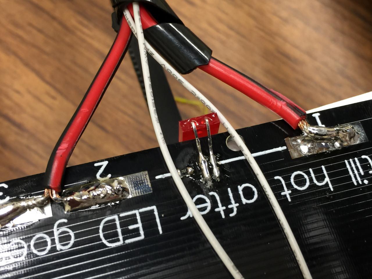
The original hotbed does not come with the typical LED heating indicator that you usually find on the 3d printer hotbeds of this type. It was probably left off because the hotbed is mounted upside down and you would not see it anyways. I ended up mounting an LED and bended it up so I could have a visual indicator when the bed was being heated.
'
Instructions:
- Laser cut or print. The laser cut parts should have the enclosure holes counter sunk so the original screws can be used. If the part was laser cut in plexiglass then carefully use a larger drill bit with the drill in reverse to make the counter sinks.
- Remove the wiring from the power outlet to the power supply (note where the wires go) and then mount the power socket on the new back plate. Install any 40mm 12VDC fans with the air flowing in towards the controller and connect the fan power to the unused V+ and COM terminals on the DC power supply.
- Reinstall on the back using the original screws.
As the controller case can get warm, this mod makes a big difference. The power supply has a fan that usually draws air into the power supply and vents out the top through the fan and the (original) enclosure has air vents at the top to vent air out but no way for air to enter into the enclosure. We came up with a quick back plate that can be laser cut (why not, Jetguy has everything) or 3d printed and can be used as is or extra 40mm fans can be mounted to help pull air into the enclosure. I ended up using the top fan since it also blows across the main printer circuit board. With this mod my enclosure no longer gets warm to the touch.''
'As the controller case can get warm, this mod makes a big difference. The power supply has a fan that usually draws air into the power supply and vents out the top through the fan and the (original) enclosure has air vents at the top to vent air out but no way for air to enter into the enclosure. We came up with a quick back plate that can be laser cut (why not, Jetguy has everything) or 3d printed and can be used as is or extra 40mm fans can be mounted to help pull air into the enclosure. I ended up using the top fan since it also blows across the main printer circuit board. With this mod my enclosure no longer gets warm to the touch.
- Strip the wire ends on the fans and screw them into the terminal blocks Red to + / Red and Black to - / Black.
- Strip the wire ends on the fans and screw them into the terminal blocks Red to + / Red and Black to - / Black.
Controller Case Cooling
As the controller case can get warm, this mod makes a big difference. The power supply has a fan that usually draws air into the power supply and vents out the top through the fan and the (original) enclosure has air vents at the top to vent air out but no way for air to enter into the enclosure. We came up with a quick back plate that can be laser cut (why not, Jetguy has everything) or 3d printed and can be used as is or extra 40mm fans can be mounted to help pull air into the enclosure. I ended up using the top fan since it also blows across the main printer circuit board. With this mod my enclosure no longer gets warm to the touch.'' '
- Cut the Red / Black wires going to the Extruder Cooling fan close to the original fan (if replacing the 24v fan)
- Solder the Red / Black wires from the Extruder Cooling fan to a four position (or two 2 position) terminal block on pins 1 & 2 and mark them F+ (red) and F- (black)
- Cut the Red / Black wires going to the Extruder Cooling fan close to the original fan (if replacing the 24v fan) or as close to the wire bundle giving you room to work with the wires and solder them to the terminal block if you will be keeping the fan.
- Strip the wire ends back and put two pieces of heat shrink tubing over the wire ends (before you solder them).
- Solder the Red / Black wires from the Extruder Cooling fan to a four position (or two 2 position) terminal block on pins 1 & 2 then cover with heat shrink tubing and mark them F+ (red) and F- (black)
- Cut the Red / Black wires on the Filament Cooling fan (the front fan) far enough back to reach the terminal block near the wire bundle. The wires remaining on the fan will need to reach from the terminal to where the fan is mounted.
- Strip the wire ends back and put two pieces of heat shrink tubing over the wire ends (before you solder them). If you have a larger piece of heat shrink tubing you can put both wires though to mark the pair as being the cooling fan (see photo).
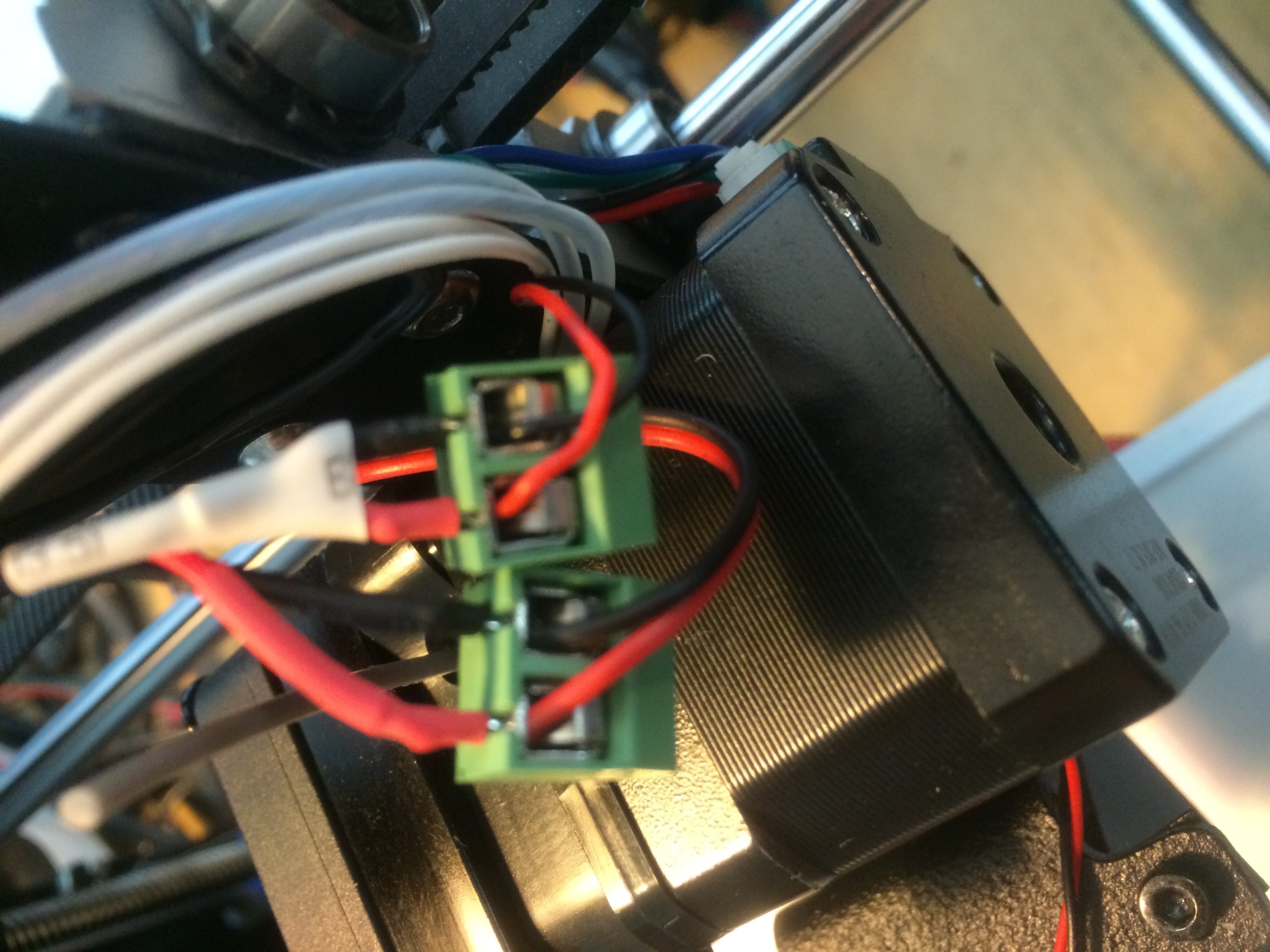
- Solder the Red / Black wires from the Filament Cooling fan to a four position (or two 2 position) terminal block on pins 3 & 4 then cover with heat shrink tubing and mark them C+ (red) and C- (black).
- Strip the wire ends on the fans and screw them into the terminal blocks Red to + / Red and Black to - / Black.

Heatbed modded with LED
Heatbed modded with LED

Cooling Fans with Terminal Block
Cooling Fans with Terminal Block
Cooling and Extruder Fan Connector
'While i think replacing the fan with a 12V is probably the best answer, this might be out of some folks skill set since the wires to the fan are soldered and heatshrinked at the entrance to the cable chain just above the extruder.'
If you can solder, great, then the best thing long term is place a screw terminal block on the wires making connecting any fan or replacement fan that much easier in the future. Obviously the fan is red and black wires so just match colors.
Instructions:
- Cut the Red / Black wires going to the Extruder Cooling fan close to the original fan (if replacing the 24v fan)
- Solder the Red / Black wires from the Extruder Cooling fan to a four position (or two 2 position) terminal block on pins 1 & 2 and mark them F+ (red) and F- (black)
- Solder a 1K surface mount or standard resistor with leads bent to the single resistor location on the bottom side of the board near the power wires.
- Solder a LED (surface mount or standard LED bent so you can see it from the top) to the double set of pads next to the resistor. The Anode or long lead should be towards the Red power wire.
Extra Mods
These mods are strictly do at your own risk and are not required. We just like to push things to their limits.
Heatbed LED Mod